Flex Board PCBs Are Different From Flexible PCBs
In the past 30 years, portable electronic devices have become progressively smaller. Thanks to innovations like flexible PCBs, these devices can now be compact and durable, with the ability to fold and bend to fit tight spaces. Moreover, these flexible circuit boards can support a higher conductor density than traditional rigid or flexible PCBs and offer enhanced reliability in harsh environments.
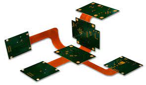
The primary difference between a flex board and a rigid or flexible circuit board is that a flex board has multiple layers of copper and a protective solder mask. As a result, it requires a different manufacturing process than a rigid PCB.
First of all, manufacturers use a special base material known as Polyimide to bond the different copper layers together. This Polyimide doesn’t require an adhesive to bond with the copper, which improves the reliability of the circuit board. To cover and protect the conductive copper surface, manufacturers use a layer of Polyimide film called a coverlay. This polyimide acts as an insulator to prevent signal interference and is applied in much the same way as a solder mask does for conventional PCBs.
To reduce stress and failure points in the copper traces, manufacturers can add a dielectric stiffening layer to the flex circuit. These stiffening layers help stabilize the conductor pattern and provide a more stable platform for component mounting. To further improve the stability of a flex circuit, manufacturers can also incorporate a rigid area on the PCB. This stiffener is laminated to the flex portion and offers more structural integrity to areas like edge connectors or mounting holes.
How Flex Board PCBs Are Different From Flexible PCBs
Another key design consideration for a flex circuit is understanding the effects of temperature fluctuations and vibrations on the traces. To mitigate the impact of these variables, a designer should stagger traces as much as possible. This will prevent the copper traces from I-beaming due to the stresses of bending and limit their failure rate. It’s important to note that flex circuits can fail due to excessive stress and heat, as well as poor design.
A common mistake that designers make with flex circuits is placing too many components on the flex portion of a PCB. This can lead to a high layer count, which increases the cost of manufacturing. It’s also important to consider whether your PCB will require pad-only plating (button plating). This method involves depositing only copper on the pads or vias, which allows for more controlled impedance.
While a flex circuit is more complicated to manufacture than a rigid board, the added flexibility and reliability can be worth the extra effort. To make sure your flex circuit is designed properly, consult with your CM’s engineering team for the best advice. They can also guide you through the process of choosing a multi-layer flex board pcb or a rigid-flex board.
A flex PCB is also capable of bending in multiple directions, which is beneficial for the Internet of Things (IoT) ecosystem. For example, smart speakers are often built on flex PCBs because of their flexibility and power efficiency.